Article 2
C
hip Thickness Screening (CTS) has proven to be a boon to pulp mill operations, reducing costs, improving productivity, yield and overall operational efficiency. Explore Acrowood’s full screening solutions. How does chip size distribution make all of this possible? And how can the chips be physically sorted and separated in order to achieve these benefits?
A blend of chips is normally sent to the digester en masse, mixed as large, medium, and small individual wood particles. Liquor is added and the cooking process progresses, with each particle being affected by the local chemical, temperature and pressure environment in which it exists, eventually releasing fibers and creating wood pulp.
Small chips cook quickly, with the penetration of liquor into the chips from all directions occurring at an equal rate – as rapidly from the chips’ ends the liquor is still able to penetrate to the center of the chip by the end of the cooking cycle, liberating the fibers and completing the process. There is a thickness, however, which represents the maximum penetration
distance for a given wood species, alkalinity of liquor, temperature, pressure, and time above which the fibers are not liberated. This means that at the end of the cooking cycle there is a small amount of wood still left uncooked at the center of the chip, with the fibers still attached to one another. When these wood particles are small they are called “shives” in the pulp, and can be screened out by pulp screens. When they are larger, as from very thick chips, they are called “knots” and are removed from pulp by special knot removing screens called knotters, representing a costly loss of efficiency and value in the system.
The point of CTS is to deal with the chips that cause these losses before they get into the digester. DiamondRoll® Particle Screens provide targeted separation of mid-sized particles (pin & particle chips) that can otherwise compromise pulping consistency.
By separating chips that exceed the pulping system’s processing ability and treating them while they are still chips, CTS allows the digester to process more chips, make more pulp, and produce higher pulp yield (as a factor relating to the chips used), saving time, energy, and money. A lot of money
In many cases the digester’s operation has been tailored so that the amount of knots and shives is kept to a level that the downstream screening and processing equipment can handle. When large chips are processed by CTS, the levels of shives and knots falls, allowing the digester’s operating parameters to be reduced (using less temperature, pressure, and time) which results in significant improvements in overall yield. The overall system savings can be significant.
History of Overthick Chip Screening
In the earliest attempts to separate the largest chips and chunks, disc thickness screens were adapted from scalping screens. Learn more about our Disc Thickness Screen. Scalping screens are high capacity, shaft-based machines with spacers separating individual discs down the length of the shaft. The intent is to let the majority of chips pass quickly between the discs, sliding between discs and over the round surface of the spacers. The discs are used to provide a motive force for the chunks and overs that need to be removed. Lobes or starshaped discs have been used depending on the material. Lobes were generally used in bark or fuel applications and star-shaped discs were used in applications involving chips.

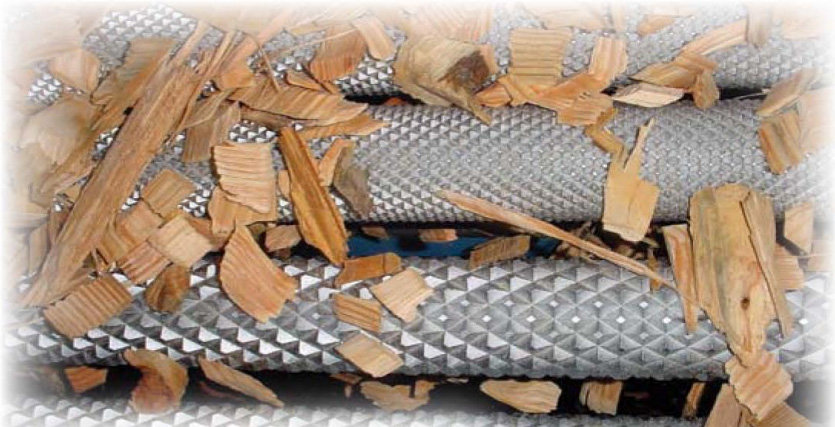
DiamondRoll® Screens orient accept chips to the opening, and reject overthick chips, sticks, and strings.
Disc Scalping Screens Scalping screens typically have an interfacial opening (IFO) of between 0.5 and 6 inches. The overs intended to be rejected are typically larger than the IFO by 0.25 to 1″ and are related to the spacing chosen for the application. A screening target to reject +2.5″ material would typically result in the use of a scalping screen with an IFO of 2″, for example. Other factors figure in to the analysis: slot length or open space between adjacent shafts, design of the disc itself (lobed or star, and the depth of the lobes or points), accuracy of separation needed, likelihood of damage due to foreign objects and contaminants, thickness of the discs (typically ⅜” to ¾” thick), rotational speed of the shafts, screen angle, and other factors. The first attempts to use discs to screen chips for thickness at a reasonable CTS target of 8 mm (roughly 1/3”) occurred in Oregon in the late 1970s.
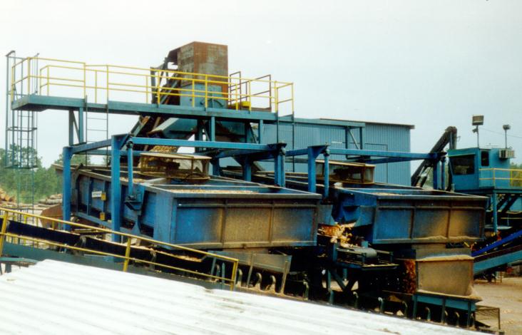
The HD Disc Scalping Screen handles heavy-duty, high-capacity pre-scaling to protect downstream CTS equipment.
V-Screens for Chip Thickness
Arranging the disc screen shafts parallel to the flow of overs and creating a deep trough where shafts turned from the bottom of the trough towards the top resulted in the so called V-screen design. The last new installation in North America occurred in the early 1990s, and, for the most part, these screens have been replaced by other, newer designs.
Flat Disc Thickness Screens
Another arrangement involved a screen frame where disc screen shafts were arranged in a parallel array, all turning the same direction from the
infeed end to the discharge. To increase capacity it is possible to lift every other shaft to create an undulating pathway for accepts and overs chips, in the raised-roll configuration. It is also possible to lift the end of the screen to hold some chips back for additional dwell time. Both of these techniques increase capacity and suppress surges in the feed flow.
Since the flow of material is spread out across the full width of the shaft, this design avoids much of the problem of concentration of wear. The first one or two shafts may wear, but not a large part of the screen. The shafts are held by a bearing arrangement that allows the shafts to be positioned so that the discs are as centered as they can be, improving the IFO accuracy of the screen. This design is still in use in many mills.
Disc screen shaft technology has been improving over the years to the point that shafts are now about as inexpensive and long lasting as they can be. Welded disc styles are popular for their strength and affordability. Shafts using discs and spacers allow the use of exotic metals for the discs, increasing their service life. In the current climate of metal shortages and skyrocketing metal prices, long life is more important than ever.
Disc screen shafts have the disadvantage of IFO accuracy control, with an overall effect of creating a minimum standard deviation of IFO for disc screens of about 0.4 mm around a mean IFO in the 6.5 to 8.0 mm range. What this means is that direct measurements of the IFO using special tools will create a data set whose mean is 7.2mm with a standard deviation of 0.4 mm. Individual nips may have deviations that are above or below this number, but overall, this is what is often observed.
Data has been gathered by mills that monitor this important characteristic of disc screens over time. Without careful attention to shaft positioning and disc wear, it is possible to demonstrate that the IFO accuracy of a disc screen will deteriorate over time, from an as-installed condition of 0.4mm standard deviation, to 0.8mm after 12 months, to 1.2mm after 18 months, to 1.5mm after 24 months.
Overthick removal efficiency follows a similar pattern. Since the value of CTS to the overall system is dependent on the accuracy of the screen and the efficiency of overthick chip removal, this deterioration is significant to the long-term success of the installation.
Rotary Screens and Chip Thickness Control
It is possible to approximate chip thickness screening and control by other methods. For example, there is a general relationship between chip length and chip thickness. Screening for length will also screen for thickness, especially at the upper end of the size distribution.

Discs interleave to form the space through which accept chips pass. The alignment of the discs and the positioning of the shafts are critical to maintaining accurate openings.
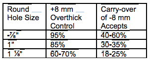
Using mixed softwood chips and a standard rotary screen, the overthick removal efficiency by accept carryover data in the table above was developed. While a high degree of overthick control is possible using a rotary screen with a small hole top plate, an additional screen is necessary to reduce the accept load to the over-thick chip processing machinery to a tolerable level. The approach of using a rotary screen as a pre-screen for thickness control is used in the patented Weyerhaeuser Process for chip thickness screening, where typically a disc or roll screen is used after the rotary screen to separate overs from accepts. Learn more about our Dual Drive Rotary Screen.
The table shows that as hole size is reduced to the point where 95% of the overthick are rejected, about 50% or more of all infeed chips are also rejected. This high flow of chips can be processed in total in some overthick chip processes (by a chip cracker, for example).
Bar Screens
Reducing a disc screen to its elemental components, a screen was developed that created a continuous slot for passing the acceptably small chips. This screen is called a Bar Screen, and is composed of parallel bars set into two rotating frames. The frames move in 180 degree opposition, producing a balanced condition within the screen frame. Chips are agitated by the motion of the bars, which are tilted down at an angle to move the overthick chips to the discharge. Bar screens are like disc screens in that they are generally
rectangular in shape, and require good distribution across their width for best performance.
Accuracy of opening for bar screens has been less than for disc screens. The bars are supported from below on metal arms that attach to the rotating frame. The arms can bend, and the bars tend to bow over their 6 to 8 foot lengths, as well as vibrate side-to-side and create a matrix of openings that allow large chips to pass into the accepts. Bar thicknesses of 6 to 12mm have been used to limit warp and damage.
Roll Screens – a different approach
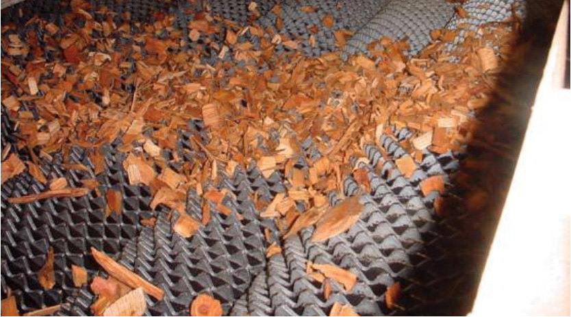
Using a completely different approach, a screen called a DiamondRoll Thickness Screen has been developed for removal of overthick chips. By employing a chromed solid shaft cut with a diamond pattern, it is possible to move chips from the infeed end to the discharge, presenting each chip on edge many times to an accurate gap between the rolls. The DiamondRoll® Thickness Screen achieves ±0.15 mm inter-roll opening stability using precision-machined rolls. The key is that the diameter of the roll is such that the chip moves over it and down the side, ending up with the edge or thickness dimension pointing directly at the space between the rolls. If the chip is thin enough to pass through, it does. If it is too thick the next roll picks it up and moves it further down the screen. What happens is that the fines and pin chips fall through most quickly, with the near sized chips often needing several attempts at being gauged before passing through. DiamondRoll® Fines Screens deliver high-precision removal of fines and pin chips with robust throughput.
Overthick chips accumulate on the surface of the screen and are sent off the end.
The big advantage of the DiamondRoll screen is that the solid steel rolls are set in the frame of the screen in such a way that the opening dimension is highly uniform. The standard deviation of the IRO (inter-roll opening) in this screen is often less than 0.15mm around a mean of 7.5mm for 8mm chip thickness control. Since the shafts don’t vibrate and are not subject to bending or damage, the IRO is consistent over the operational life of the screen. When wear of the chrome does occur it is possible to rechrome the shafts to bring them back to as-new condition.
An additional benefit is that the shaft support and drive system allow the shaft positions to be easily moved or adjusted, making changes in the IRO simple to make. Often a mill will experience changes in chip quality, wood species, or digester condition that will suggest a change in thickness control point, and this design allows changes easily.
Mill Experiences with CTS
As this technology was first being applied, a number of published summary papers recounted the measurable effects it had in the mill. As the value was being recognized, there was a significant movement to install systems into mills where previously there was little to no attention paid to chips or chip quality. The results were dramatic and positive in almost every installation.

Rotating sets of bars create an opening for accept chips to pass.
As we sit today, 25 plus years down the road, many of these early systems have undergone a number of upgrades and improvements. Worn out or poorly performing equipment has been replaced. The attention to chip quality that energized the pulp mill has moved into the woodyard, and often into the wood procurement organization so that there is a company-wide focus on wood and chip quality. Suppliers are being pressured to improve their chip quality, and attention is being paid to sawmill chip sources, chip mills, and on-site chipping and chip handling systems.
Chip thickness control has been extended from Kraft pulping systems to sulfite, and even mechanical pulping systems, using the reasoning that chip uniformity can only improve these other processes. Their experiences with expanded chip quality control have been very positive. Payback analyses in many installations have proven the value of screening and chip quality control. Overall, CTS is riding a wave of popularity based on a track record of success.
Future of Chip Thickness Control
Where do we go from here? In terms of thickness control, most mills in North America who can benefit from CTS have installed some form of chip control. In many cases, newer technologies exist that could improve screening efficiency and flexibility of operation. In many mills the original screening room is completely worn out and in need of wholesale replacement. Maintenance has been lax or non-existent in some mills. Our knowledge of the benefits of CTS has progressed to the point that paybacks for individual pieces of equipment can be developed, if needed, to help justify replacements or up-grades on an individual basis. So, to maintain or extend thickness control is possible, with benefits to the mill being clear and demonstrable. Acrowood’s lineup also includes the Trillium® OSB Strand Screen, ideal for managing long, slender OSB strands not covered by typical CTS systems.
Please let us email us this Case Study and any other you need.

