Article 3
O
verthick chips have a negative impact on digester performance. They reduce yield, produce shives and knots, and rob capacity in the digester by displacing smaller chips that could have produced pulp. Processes have been developed to selectively separate overthick chips from chips of acceptable thickness, and methods to render these large chips acceptable have been employed. Several dominant mechanisms have been employed as reduction methods, creating persistent issues of processing efficiency, maintenance requirements, and cost.
Rechipper
A rechipper is a machine that cuts wood in an un-oriented way. Chips fall down into a slanted spout in a random manner and are finally cut by knives mounted on a spinning chipper disc. Ideally, they would be oriented so that the long axis of the chip would be perpendicular to the cut, and the resulting 2 pieces would each be half the length (approx.) of the original chip. Many chips are cut at 90 degrees to this orientation so that the thickness and chip length are not affected at all, and nothing helpful to pulping actually happens. The randomness of the cutting action is what causes problems here: the fines and pins levels produced are high, but the ineffectiveness of reducing overthick levels is what renders rechippers unacceptable for pulp mill operations. Learn more about the Acrowood Rechipper.
This classic machine has seen its best use in processing overs generated in saw milling applications prior to the pulp mill. When generally large chips (+2″ round or square hole, and larger) and gross overs can be separated by a rotary screen, a rechipper is a good way to chop these up into smaller
pieces before they are sent to the pulp chip van for transport. Where the pulp mill chip buyer has established a size specification that limits the percentage of oversized and gross overs chips to a maximum allowable number, the use of the rotary screen/rechipper combo can typically achieve this with sufficient reliability.
Chip Slicer
A machine has been developed whose purpose is to reduce a chip in its thickness dimension from overthick (greater than the specified maximum thickness of 8 mm, typically) to acceptable thickness (less than 8mm). This machine was called a Chip Slicer, and was adapted and redesigned around the original concept of a knife ring flaker. Any chip that is processed by a Chip Slicer passes between a knife and a gauge plate, each set in such a way as to produce a 6.5 mm thick slice, with any remaining amount sliding on the inner surface of the knife ring to the next knife. This remainder is pushed along by an anvil, mounted to a rotor spinning inside the knife ring. This machine has served the pulping industry well, versions having been made by various companies in several designs, but having an overall installed base of greater than 400 units by the mid-1990s. The beauty of a Chip Slicer is that a chip cannot exit the machine without being cut down in thickness to the target size. The efficiency of overthick reduction is greater than 95%. This means that of all the overthick chips entering the Slicer, fewer than 5% remain in an overthick condition as they exit. For a woodyard machine to have this capability is remarkable, especially since the benefit of this –
The Acrowood Chip Slicer is a powerful solution designed to convert overthick wood chips—those exceeding 8 mm—into mill-ready pulp material below 8 mm. Using a precision knife and gauge plate mechanism within a rotating knife ring, each chip is defined to a consistent thickness with over 95% accuracy. Chip Slicer offers exceptional reliability and performance—ensuring compliance with buyer specifications and improving overall yield.
Chip Slicer
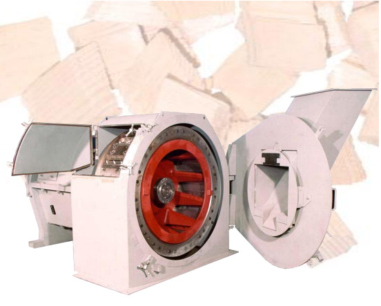
A Chip Slicer is composed of two rotating elements. The red anvil rotor turns relatively fast and pushes the oversize chips into the knives. The outer knife ring holds 15 angled knives, which trim the overthick chips to the desired thickness.
Chip Slicer - Anvils
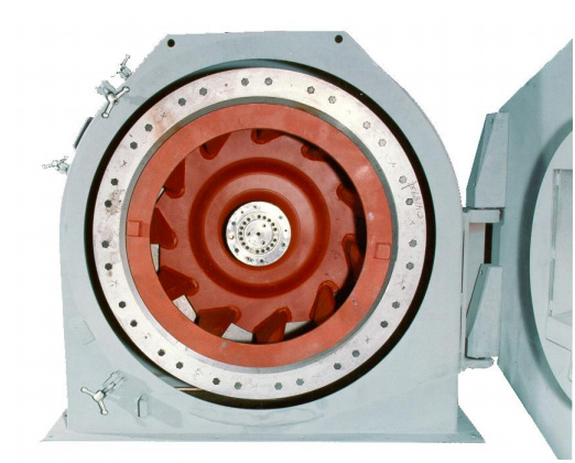
The anvils are mounted on the anvil rotor at an angle to provide a sweeping forward action.
Overthick Chip Treatment Methods
| wdt_ID | Method | Efficiency | Maintenance | Relative Purchase Cost |
|---|---|---|---|---|
| 1 | Rechipper | Overthick reduction: 65% Fines generation: 5% Pins generation: 25% |
Knives to change, anvils to keep sharp: (weekly access at least). |
Inexpensive |
| 2 | Chip Slicer | Overthick reduction: 95% Fines generation: 1.5% Pins generation: 12-15% |
Knives to change, anvils to change: (access every 3-7 days) |
Moderate |
| 3 | Chip Cracker | Overthick reduction: 95% Fines generation: 0.5 % Pins generation: 1% |
Segments last 30-60 months: (lubrication maintenance only) |
Expensive |
| 4 | Chip Sizer | Overthick reduction: 65% Fines generation: 1-2% Pins generation: 3-5% |
Hammer lasts 24-36 months, discharge grate 12 months | Inexpensive |
| 5 | Chip Sizer (Horizontal Disc Chipper) | Overthick reduction: 80% Fines generation: 1.5% Pins generation: 12-15% |
Knives and anvils to change: (access 3-7 days) |
Expensive |
Overthick Chip Treatment
effort would show up in the pulp mill and its effects were noticeable and immediate. Shut the Slicer down and pass overs straight to the pulp mill, and the pulp mill operators would be calling the woodyard within minutes to know the reason!
Chip Slicers have two general deficiencies that have been addressed in later machine designs. Slicers generate fines and pins at a consistent and relatively high rate, regardless of the chip quality or size distribution of the infeed chips, and Slicers are filled with precision parts that wear and must be periodically replaced. In fact, the fines and pins generation rates are dramatically increased when the wear condition of the knife ring and anvil components have been allowed to deteriorate, so this can be a compounding effect in mills where maintenance in the woodyard is a low priority.
The combination of these deficiencies, which impact the overall yield from the Slicer (fines and some pins are often screened out after slicing) and maintenance costs (maintenance manpower is needed on a regular basis, and parts costs can be high), drove the development of an alternative method.
Chip Cracker
Chip Crackers first appeared in the mid-1990s in North America as devices to crush or compress chips, causing the fibers to split apart which allows pulping liquor to penetrate to the center of an overthick chip.
In essence an impact force is used to crush a chip in such a way as the fibers are separated along their lengths, with fiber breakage kept to the smallest extent possible.
A textured pattern on the rolls is used to ensure that the chip will be fissured regardless of the orientation it has when it enters the nip. Theoretically, a chip that is compressed by the rolls where the fibers are parallel with the nip should be squeezed in such a way that the fibers are “naturally separated” by the action of the rolls. When the chip enters at right angles, or where the long axis of the fibers in the chip are perpendicular to the nip, then the compression formed by the rolls does not necessarily cause the fibers to separate. The textured pattern on the roll surface is used to produce a force that separates the fibers regardless of their orientation.
The large rolls used in Chip Crackers have considerable mass, necessary due to the large forces generated during the compression of knots and other hard materials. This large mass is used to form a portion of the compression force needed in some designs, aided by additional hydraulic pressure to hold the rolls together to affect the thick chips. The rolls have renewable surfaces in the form of replaceable segments or roll covers, as wear and damage to the roll surface will cause deterioration of the cracking effect, in time. These segments are commonly made of stainless steel, and may include special fasteners or slippage prevention methods to resist the forces of movement that are generated during cracking.
The Acrowood Chip Cracker gently reforms overthick chips—minimizing fiber degradation, fines and pin generation—to ensure higher pulp yield.
Work with Chip Crackers has shown that wet chips crack better than dry chips, with water and sap being squeezed from the chip during the
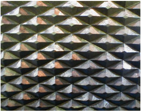
The textured surface of a compression roll needs to provide sufficient friction to draw the oversize chips into the compressing nip. The pattern shown here also fractures a chip regardless of its fiber orientation.
process. Cold and frozen chips fracture more easily than chips that are not frozen, so adjustments to the Cracker settings of nip gap and pressure are required during the coldest months. It would be necessary to increase the nip gap from 3 mm to 4mm and more, and reduce the hydraulic compression pressure in order to prevent excess chip damage when the chips are at -10 C and lower.
Chip Cracker
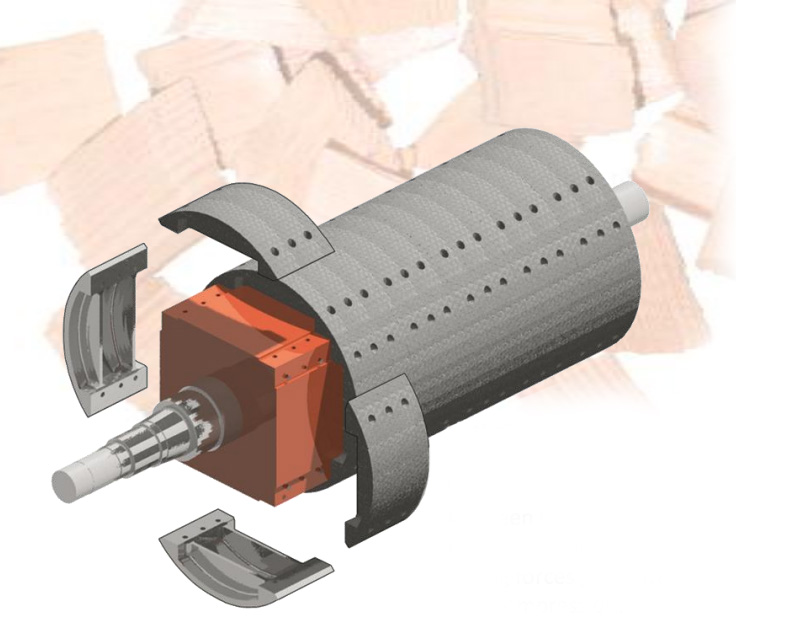
The Chip Cracker features cast stainless steel segments which are are bolted to a square support shaft. Solid connections are required between the segment covers and the supporting shaft due to the strong forces generated during chip compression.
Chips that are compressed to less than one third of their original thickness show very little evidence of cracking: a 6mm chip compressed to 3mm shows almost no cracks, for example. Likewise, these thinner chips show no surface or edge damage, and no fines or pins can be attributed to their passage through the Cracker. (Recall that every chip that passes through a Slicer, even thin ones, generates fines and pins at about the same rate as an overthick chip.) Chips larger than three times the nip dimension are cracked with increasing severity, with larger chips showing the greatest effect. A 15mm chip passing through a 3mm nip will be cracked and fissured extensively.
Consequently, one of the advantages of the Cracker is that having some degree of accepted chips mixed in with the overs does not adversely affect the fines and pins generation rates and that the largest chips are the most changed in the cracking process.
Machines to perform chip compression commercially are available from only a few sources. They vary in some significant ways, including horsepower employed, drive design, roll support design, roll shaft, and segment design, and roll surface patterns. Many of these differences can have profound impacts on processing performance. Capacities range to 100 tons of overthick chips processes per hour.
Chip Sizer (based on a hog design)
Unfortunately two manufacturers have marketed machines with the same trade name, and they are of very different types. They are both known commercially as Chip Sizers. One is by the Jeffrey Specialty Equipment Corporation and is based on a hammer hog concept modified for use on overthick chips. A specially designed hammer is used to impact chips across an internal grate fit with raised ridges. As the hammers propel the chips against the ridges the oversized and overthick chips are “gently knocked apart”, according to the manufacturer. By keeping the internal tolerances large enough the hammers don’t actually abrade the chips to any great extent; so that the acceleration used by the turning rotor is enough to affect some breakdown of the large chips.
Field performance of this method is less than Chip Slicing or Chip Cracking but may be sufficient for some processes that do not require complete chip thickness control. Larger chips are reduced more than smaller ones. Small chips may pass through this Sizer without noticeable damage. The capacities of this Sizer are similar to Chip Slicers. And most importantly, this design eliminates the need for periodic maintenance. There are no parts that need weekly attention or replacement. And this machine has the classic “hog” resistance to damage from tramp metal.
Chip Sizer (based on a disc chipper design)
The second Chip Sizer is by the Andritz Company and is based on a disc chipper design. In this machine the disc is turned horizontally with the knives facing up. Anvils are fit in various places in the top casing, so that chips that are fed into the center of the turning disc are chipped as they slide across the face of the chipper.
Efficiency of over-size chip reduction is claimed to be 80%. Fines and pins generations will be similar to those produced in a Slicer. Currently in North America there is only a single Andritz Chip Sizer in operation.
Future of overthick chip processing
High-efficiency overthick chip screening systems require efficient processing methods for reducing overthick and oversize chips to an acceptable condition. The development of the Chip Slicer was a boon to pulping system processing as it physically reduced overthick chips to an acceptable size. The great Achilles heel to slicing was always the generation of fines and pins. That, coupled with knives and anvils which required periodic changing ultimately relegated this technology to a second tier of priority. The advent of compression technology allowed overthick chips to behave like accepts in the digester without the generation of fines and pins. Designs that overcame the inherent difficulty and incompressibility of the knots and oversize chips have allowed mills to achieve the ideal condition: reducing oversize to acceptable properties without expensive and periodic maintenance. The Chip Cracker available today, with its heavy duty roll segment covers, textured patterns, and simple hydraulic compression system has effectively replaced the Chip Slicer in the market.
As the industry tries other experimental technologies in an attempt to evaluate alternatives to the Chip Slicer and Chip Cracker, these new technologies will be judged on their abilities to produce an acceptable chip without fines and pins generation, and without maintenance. High efficiency in oversize reduction will be mandatory.
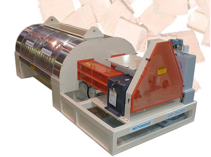
The motor and drive system of the Chip Cracker powers the rolls together to form the compression force. Included within the enclosure is the hydraulic package which draws the rolls together. The additional compressive force is required to open the spaces between the fibers.
Explore Acrowood Chipping Solutions
- Acrowood Chipping Overview
- Whole Log Chipper
- Slant Disc Chipper
- Veneer Chipper and Feedworks
- Rechipper
- Chip Cracker
- Chip Slicer
Let us send you this Case Study and any others you need.
